EctoLabs' Standalone Hero(ish) Thrower Build
Posted: September 14th, 2021, 4:58 am
Ever since my Ghost Trap build went quite well last year, I've been wanting to do another detailed prop build with all the bells and whistles. The obvious thing I am still missing is a pack, but I just don't have the time or the space for one at the moment. So, what about the Neutrona-Neutrino-Particle-Proton-Wand-Gun?
From this point, I'm just gonna call it the 'Thrower' because, let's face it - 'Wand' sounds a little too Harry Potter these days as well as being far too funny a word for someone with a childish sense of humour... like me. It may be a component part of the overall pack, but it's still a really interesting prop in its own right. Plus, it has tons of flashing lights, switches and buttons - and who doesn't love those?
Therefore, I've decided to build a completely standalone thrower from scratch with fully custom Arduino-based electronics. I want this to include include lights, sound and haptics with different FX modes, and be as visually accurate as possible according to the reference photos of the screen-used props. Sound effects will be self-contained as with the Matty and Hasbro wands, but with the ability to hook it up to a full pack at a later date. I'll use some 3D printed parts, but include as many metal components as possible. This also means incorporating a pop-mechanism via the green lever and a twisting (non functional) barrel.
----------
How hard can it be? Let's find out........
----------
Firstly, I began by looking for accurate 3D print files. There's no point in modelling the thrower from scratch if someone else has already done a great job. A search on Thingiverse brought up a few good looking models, so I did a few quick comparisons between the 3D parts of two or three models, and the tape-measured Sony Lobby reference photos here on GBFans. In the end I settled for notsabbat's files which seemed pretty consistent with the dimensions of the screen-used throwers as well as being better designed for use with aluminium tubes. You can find the set of files I used here: https://www.thingiverse.com/thing:3885923.
First up, was the main gun box. There are a few things I want to adjust with this model, but as I am working this all out as I go along, I opted to go ahead and print as is - any alterations can be done manually as I learn more about how the original props were designed and built.
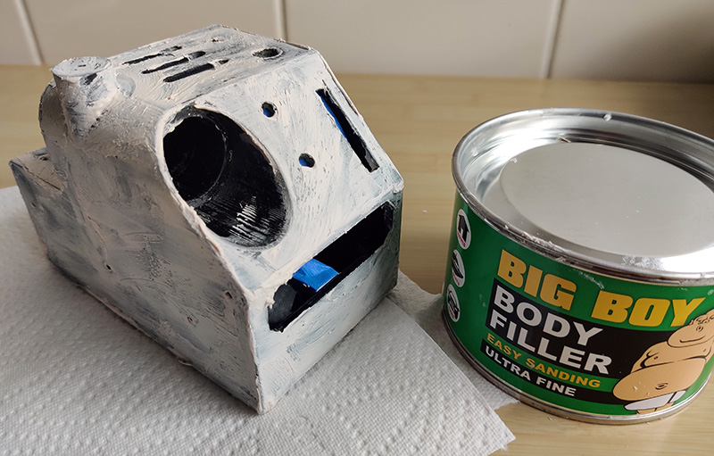
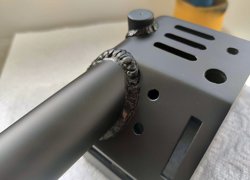
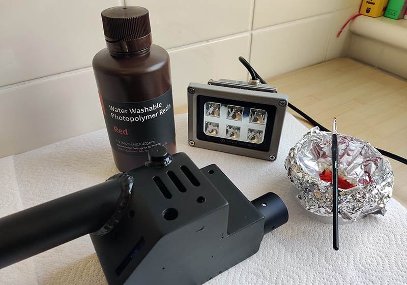
The gun box was a long print, but came out perfect first time. I decided to print at relatively low resolution as I plan to smooth all the parts with a combination of body filler, filler primer and possibly UV resin. I printed this at 0.3mm layer height which produces quite prominent layer lines, but saves a considerable amount of time.

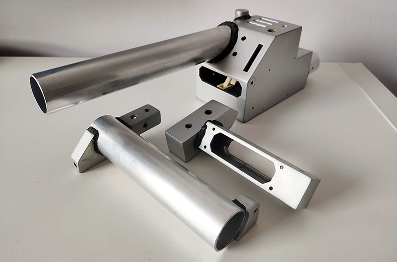
I also printed the wing parts, the barrel lock, the fuse and control boxes and the front grip (which I modified slightly to better match the length of the grip on the reference thrower - this should be slightly longer than the rear grip which I will come to later).

POP-MECHANISM & BARREL TWIST
Something of a mystery to me at this point was how the pop-mechanism was originally designed, but it was clear that it was the green lever that controlled this and not by the twisting of the barrel. I concluded that I would need three different sized aluminium tubes to make up the inner, central and outer sections. I had originally purchased three tubes with the same wall thickness, but a slight error in my calculations meant that one did not fit inside the other. In the end, I retained the largest tube and sent the other two back to the seller. I replaced these with an extending curtain pole which I found in a cupboard in my apartment. By chance, they were the perfect size and also allowed for easier cutting due to them being much thinner. They were painted white, but some acetone should be able to sort that out later on.
To assist in working out the mechanism, I measured the diameter of each tube and mocked up the barrel assembly in CAD so I could work out a design visually before doing any cutting and drilling. Thanks to the several existing pop mech kits out there, plus details of how the originals worked, I was able to come up with my own variation...

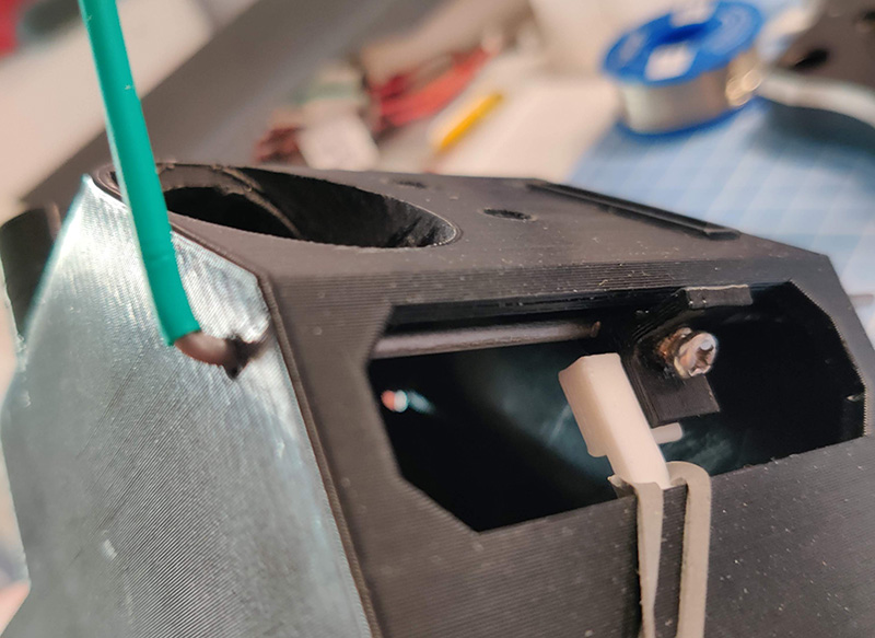
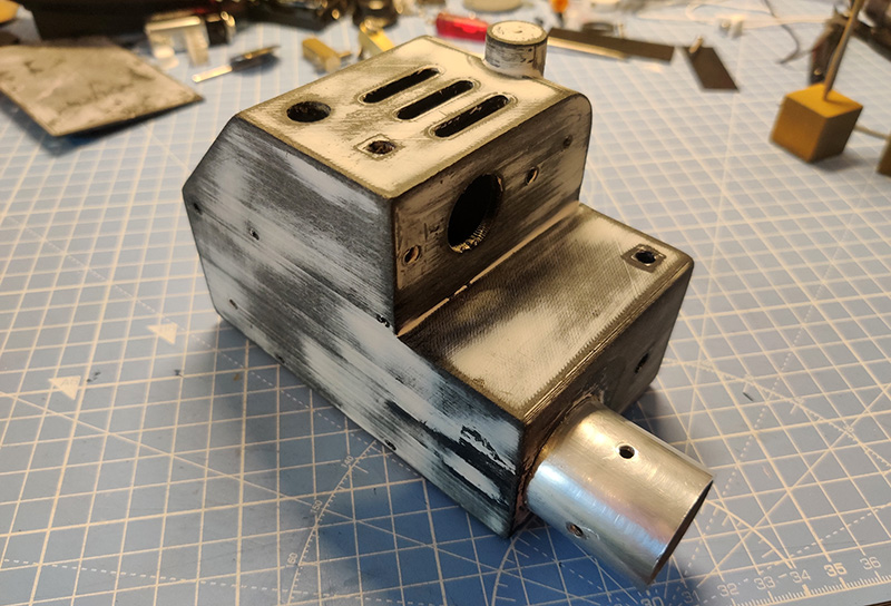
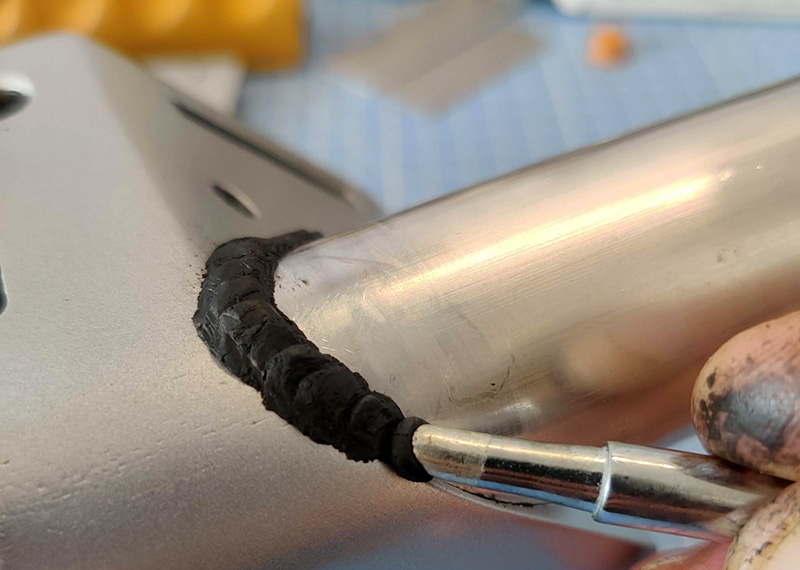
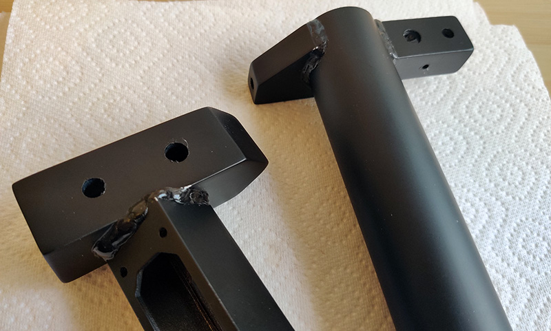
The outer tube is 33mm in diameter (with 1.6mm wall thickness) and is cut into two sections. The first section is 75mm in length and has two holes drilled - one at the very top and the other at 90⁰ on the outside edge. This section was then attached permanently to the gun box. I needed to dig out the large hole in the front to allow the tube to pass right through:


This made it pretty rough as it exposed a lot of 3D printed infill, but a heady mix of filler, grab adhesive and super glue made sure that tube wasn't going anywhere. The most important thing was to make sure it was attached straight with the holes positioned in the correct place, otherwise the rest of the barrel would end up looking very wonky.

The central tube is 28mm in diameter (with 1mm wall thickness) and has holes that line up with those in the outer tube, so the two can be bolted together. I then drilled two more holes in the same positions, only further down the tube. I used a hacksaw blade to cut out the section between these two holes to create a rounded slot - this is needed for the barrel twist. I removed most of the white paint by immersing the tube in pure acetone - this loosened the paint until it was possible to peel it off cleanly in large sections. I then added some electrical tape to increase the diameter of the tube in order to remove any wobble when inserted into the outer tube.

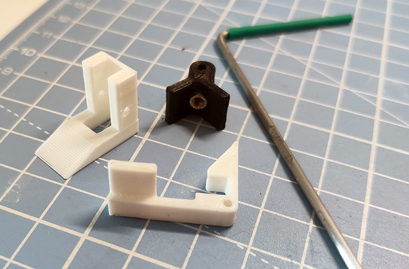
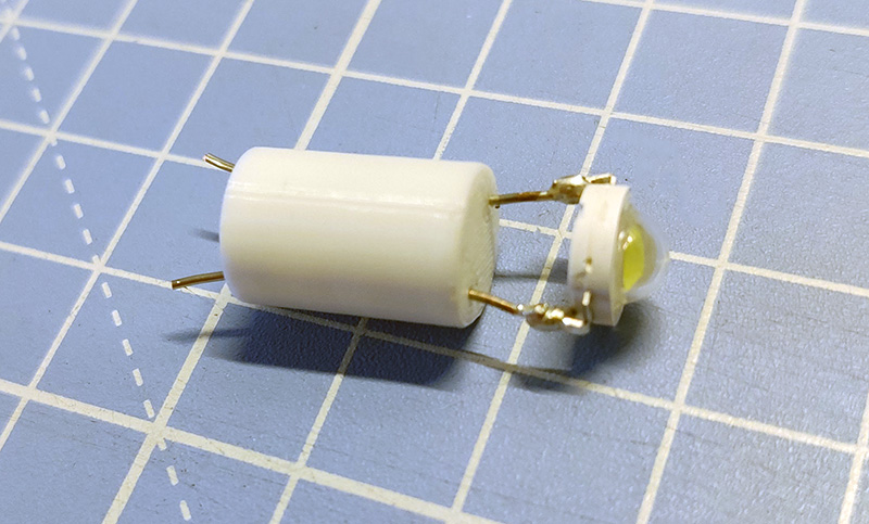
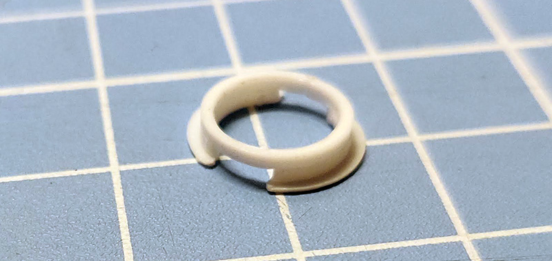
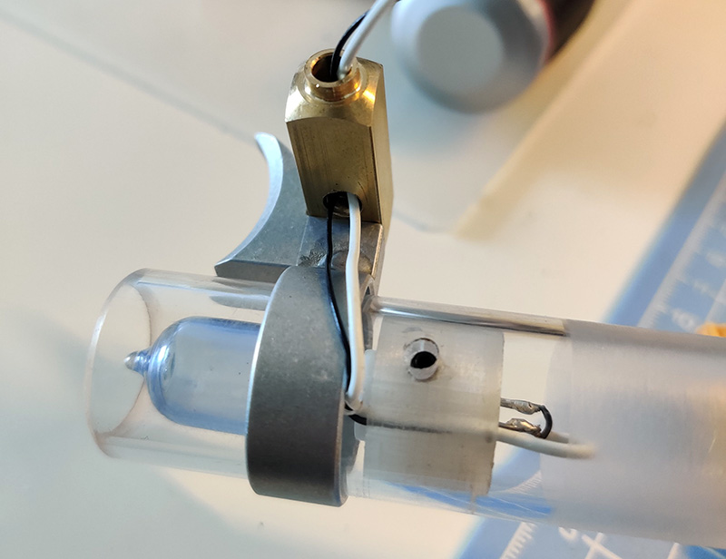
Thinking of the mechanism as a whole, I knew I needed somewhere inside the barrel for an elastic band or spring to be secured. With this in mind, I designed a 3D printed piece that would hold a band in place, as well as doubling as a nut for the two bolts that fasten the outer and central tubes together. Because of its shape, I call it the 'pacman nut'. I glued in some M3 brass threads to prevent the holes from getting stripped:

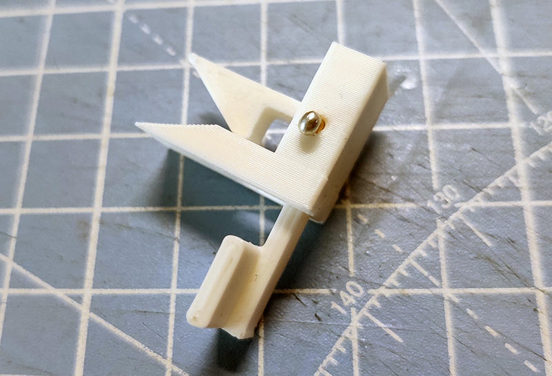
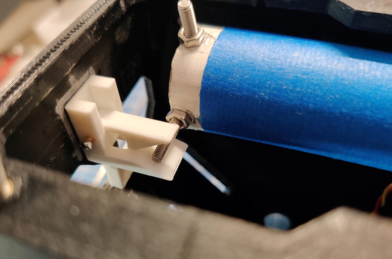
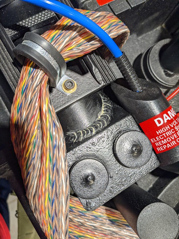
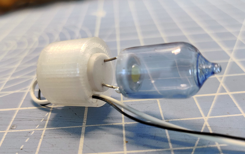
When secured in place, there is a gap around the rest of the pacman nut to allow the inner tube to run freely up and down the central tube, with a cut out to allow the wires from the barrel LEDs to pass through without getting caught. The photo below shows the pacman nut in place securing both the outer and central tubes together (this shot was actually taken before I glued the outer tube into the gun box so it's easier to see). One of the securing bolts runs straight through the pacman and a square hole in the centre means an elastic band can be wrapped around the bolt.

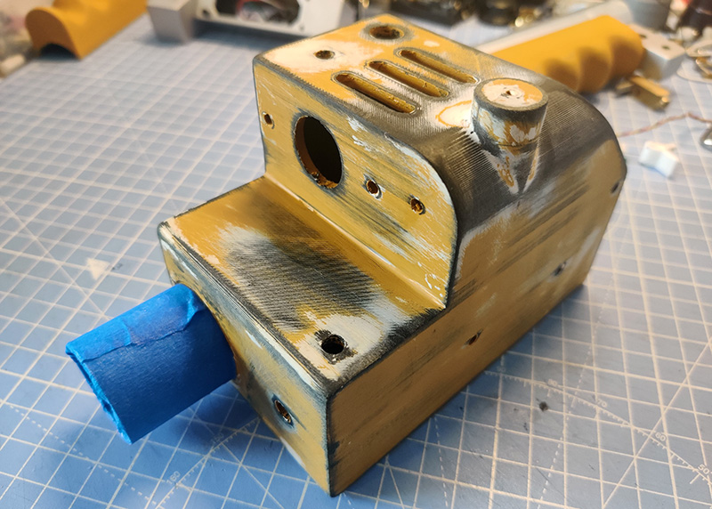
The second section of outer tube is 150mm in length. This has just one hole that lines up with the slot in the central tube. My original intention was to add a bolt through these holes under the grip, but while routing through my nuts and bolts box, I found a metal dowel (supposedly from an Ikea bookcase to hold a shelf in place). Glueing this into the rear of the grip itself meant I could position the grip on the outer tube perfectly every time (the grip you can see below is after it had a coat of yellow filler primer - ignore that for now as we'll get to that later). The dowel passes through the hole and allows this section of outer tube to be rotated for the length of the rounded slot in the central tube behind. It also prevents the outer tube from slipping off. Win win!!

Finally, the inner tube is about 25mm in diameter (with a 1mm wall thickness) and is 230mm in length. I have cut away half of the tube for 180mm of its length, leaving 50mm at the end intact. Removing this section means that it can travel up and down the central tube without colliding with any of the securing bolts. I made two holes at the rear end - these are for a bolt that will hold the other end of the elastic band, and a second bolt that will stick outward and be held by a catch that I will add later. A couple of layers of blue tape has been added to increase the outer diameter a little, and to make the tube's movement a bit smoother.

Next up... acrylic action!
From this point, I'm just gonna call it the 'Thrower' because, let's face it - 'Wand' sounds a little too Harry Potter these days as well as being far too funny a word for someone with a childish sense of humour... like me. It may be a component part of the overall pack, but it's still a really interesting prop in its own right. Plus, it has tons of flashing lights, switches and buttons - and who doesn't love those?
Therefore, I've decided to build a completely standalone thrower from scratch with fully custom Arduino-based electronics. I want this to include include lights, sound and haptics with different FX modes, and be as visually accurate as possible according to the reference photos of the screen-used props. Sound effects will be self-contained as with the Matty and Hasbro wands, but with the ability to hook it up to a full pack at a later date. I'll use some 3D printed parts, but include as many metal components as possible. This also means incorporating a pop-mechanism via the green lever and a twisting (non functional) barrel.
----------
How hard can it be? Let's find out........
----------
Firstly, I began by looking for accurate 3D print files. There's no point in modelling the thrower from scratch if someone else has already done a great job. A search on Thingiverse brought up a few good looking models, so I did a few quick comparisons between the 3D parts of two or three models, and the tape-measured Sony Lobby reference photos here on GBFans. In the end I settled for notsabbat's files which seemed pretty consistent with the dimensions of the screen-used throwers as well as being better designed for use with aluminium tubes. You can find the set of files I used here: https://www.thingiverse.com/thing:3885923.
First up, was the main gun box. There are a few things I want to adjust with this model, but as I am working this all out as I go along, I opted to go ahead and print as is - any alterations can be done manually as I learn more about how the original props were designed and built.
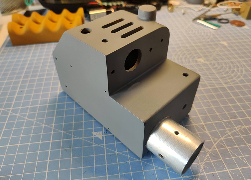
The gun box was a long print, but came out perfect first time. I decided to print at relatively low resolution as I plan to smooth all the parts with a combination of body filler, filler primer and possibly UV resin. I printed this at 0.3mm layer height which produces quite prominent layer lines, but saves a considerable amount of time.
I also printed the wing parts, the barrel lock, the fuse and control boxes and the front grip (which I modified slightly to better match the length of the grip on the reference thrower - this should be slightly longer than the rear grip which I will come to later).
POP-MECHANISM & BARREL TWIST
Something of a mystery to me at this point was how the pop-mechanism was originally designed, but it was clear that it was the green lever that controlled this and not by the twisting of the barrel. I concluded that I would need three different sized aluminium tubes to make up the inner, central and outer sections. I had originally purchased three tubes with the same wall thickness, but a slight error in my calculations meant that one did not fit inside the other. In the end, I retained the largest tube and sent the other two back to the seller. I replaced these with an extending curtain pole which I found in a cupboard in my apartment. By chance, they were the perfect size and also allowed for easier cutting due to them being much thinner. They were painted white, but some acetone should be able to sort that out later on.
To assist in working out the mechanism, I measured the diameter of each tube and mocked up the barrel assembly in CAD so I could work out a design visually before doing any cutting and drilling. Thanks to the several existing pop mech kits out there, plus details of how the originals worked, I was able to come up with my own variation...
The outer tube is 33mm in diameter (with 1.6mm wall thickness) and is cut into two sections. The first section is 75mm in length and has two holes drilled - one at the very top and the other at 90⁰ on the outside edge. This section was then attached permanently to the gun box. I needed to dig out the large hole in the front to allow the tube to pass right through:
This made it pretty rough as it exposed a lot of 3D printed infill, but a heady mix of filler, grab adhesive and super glue made sure that tube wasn't going anywhere. The most important thing was to make sure it was attached straight with the holes positioned in the correct place, otherwise the rest of the barrel would end up looking very wonky.
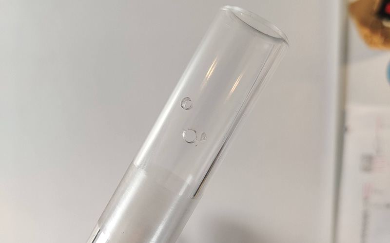
The central tube is 28mm in diameter (with 1mm wall thickness) and has holes that line up with those in the outer tube, so the two can be bolted together. I then drilled two more holes in the same positions, only further down the tube. I used a hacksaw blade to cut out the section between these two holes to create a rounded slot - this is needed for the barrel twist. I removed most of the white paint by immersing the tube in pure acetone - this loosened the paint until it was possible to peel it off cleanly in large sections. I then added some electrical tape to increase the diameter of the tube in order to remove any wobble when inserted into the outer tube.
Thinking of the mechanism as a whole, I knew I needed somewhere inside the barrel for an elastic band or spring to be secured. With this in mind, I designed a 3D printed piece that would hold a band in place, as well as doubling as a nut for the two bolts that fasten the outer and central tubes together. Because of its shape, I call it the 'pacman nut'. I glued in some M3 brass threads to prevent the holes from getting stripped:
When secured in place, there is a gap around the rest of the pacman nut to allow the inner tube to run freely up and down the central tube, with a cut out to allow the wires from the barrel LEDs to pass through without getting caught. The photo below shows the pacman nut in place securing both the outer and central tubes together (this shot was actually taken before I glued the outer tube into the gun box so it's easier to see). One of the securing bolts runs straight through the pacman and a square hole in the centre means an elastic band can be wrapped around the bolt.
The second section of outer tube is 150mm in length. This has just one hole that lines up with the slot in the central tube. My original intention was to add a bolt through these holes under the grip, but while routing through my nuts and bolts box, I found a metal dowel (supposedly from an Ikea bookcase to hold a shelf in place). Glueing this into the rear of the grip itself meant I could position the grip on the outer tube perfectly every time (the grip you can see below is after it had a coat of yellow filler primer - ignore that for now as we'll get to that later). The dowel passes through the hole and allows this section of outer tube to be rotated for the length of the rounded slot in the central tube behind. It also prevents the outer tube from slipping off. Win win!!
Finally, the inner tube is about 25mm in diameter (with a 1mm wall thickness) and is 230mm in length. I have cut away half of the tube for 180mm of its length, leaving 50mm at the end intact. Removing this section means that it can travel up and down the central tube without colliding with any of the securing bolts. I made two holes at the rear end - these are for a bolt that will hold the other end of the elastic band, and a second bolt that will stick outward and be held by a catch that I will add later. A couple of layers of blue tape has been added to increase the outer diameter a little, and to make the tube's movement a bit smoother.
Next up... acrylic action!